Disclaimer
First up I’d say in any professional environment there’s no way I’d recommend anything but “proper” PoE, that is to say 802.3af or PoE plus.
For DIY home installations, however, we can do things differently. And I don’t mean “substandard” by any means. Rather we can do them in a more tightly-spec’d way, we can design our own system of distributing power that is equally efficient in terms of power loss, and equally reliable… but far cheaper.
(The reason you wouldn’t inflict this on a corporate environment is not because it isn’t as good, but rather the next guy / girl who comes along won’t spec the replacement power supply properly, and blow something up. Also DIY jobs tend to vary in quality, whereas using PoE membrane switches and device gives a standard of power distribution quality that can be relied upon. We DIY types do things properly, we are masters of our own home, and we know how to do basic maths, so it’s okay, right?)
Preliminary
I suppose I would sing the praises of DIY PoE for the home, because when it comes to electronics I love doing things myself.
This isn’t true with computers, I can’t be bothered to faff around swapping RAM out or upgrading motherboards for my own gear any more, although I used to love doing that. Perhaps that’s because in the 90s desktop PCs were the rage and to play better games you had to have the better video card, which required knowing how to change the video card, which meant knowing how to build a computer. I don’t play games any more and I certainly don’t remember the last time I used thermal paste on a CPU. Or maybe it’s because there are no cost gains to be had with DIY computers these days.
Not so with PoE!
Below is a little chat about PoE, and at the bottom of the post I’ll go into what I am using in my wall controller project.
Most computer / network techies already know the basics when it comes to PoE, but this post seeks to shed some light on the choices to be made when considering PoE for Home Automation.
Why PoE? (Skip this if you already get it.)
Most wired network devices also need some way of powering them. Wireless Access Points, network cameras, intercom systems, control panels, they all need power – but if you are already taking a network cable to them, why not use that cable to also deliver power to them as well? Here are two benefits: no need to hire an electrician to extend your ring mains to awkward places, no ugly extra cables on wall-mounted devices to compound the felony.
Certainly in the case of my uber wall control panels, they are being sited inside wall boxes at various points in the house that don’t require power. To bring power to each panel would be a lot of extra cables in walls, and the installation cost would increase hugely. There’s spare capacity in a CAT6 or CAT7 cable, why not use it?
Active vs. Passive PoE
“Passive PoE” is a bit of a misnomer, but that aside – here’s a comparison.
Active PoE is industry standard in business, and involves sending 48V down a network cable to the device. The power usually* comes from the network switch itself, and the device has some special electronics that talks to the switch on the other end of the wire and negotiates power using a series of signals (resistance detections and presentations of loads). It’s pretty complex, and in fact PoE isn’t really one standard at all. (“The thing I like about standards is that there are so many to choose from…”)
The other thing the device must do is step-down the voltage to whatever it requires.
* Many people use mid-span injectors, that’s where the switch doesn’t supply power but you can inject power using a separate device. This gets messy if you have very many devices requiring power, but as a general rule fine for the odd one or two.
Passive PoE is a system that simply splits your ethernet cable at both ends, allowing you to place your own power supply at one end, and then connect your device power to the splitter the other end. No power negotiation – no voltage step-down.
There are shoddy implementations of passive PoE, and there are lovely ones.
A common example is where, instead of hooking up a power supply directly to where your security camera is installed, you can install a splitter at both ends. On the camera end, your splitter has a little power plug that connects to your camera (sinking power), and on the other end your splitter has a socket that connects to the power supply (sourcing power).
Active PoE – pros and cons for home use
Pros:
- Higher 48V transmission over cable means lower voltage drop-off = decreased power loss (saving money on bills).
- NB Passive PoE allows you to supply whatever voltage you like, but more often than not it’s used with existing 12V or 9V device power supplies
- Power negotiation is great because it means that a device is only allocated the power it requires; where there are more than a few PoE devices, this quickly becomes a sensible idea for all aspects of a system (cooling, conserving energy, etc.)
Cons:
- PoE switches are usually expensive (£350+)
- PoE switches are usually very noisy (bad for the home environment). You can find cheap fanless switches such as the Cisco 2960C-12PC-L or D-Link DGS-1008P/B, but most smaller switches tend to have PoE capability only on half the number of ports (e.g. 8 port switch has PoE on 4 ports).
- PoE requires your Arduino project OR your network device must support it. Network devices supporting PoE are usually far more expensive.
Re the last point, it’s possible to include some electronics that will supply your Arduino project with PoE but they cost £16 on top of the network shield:
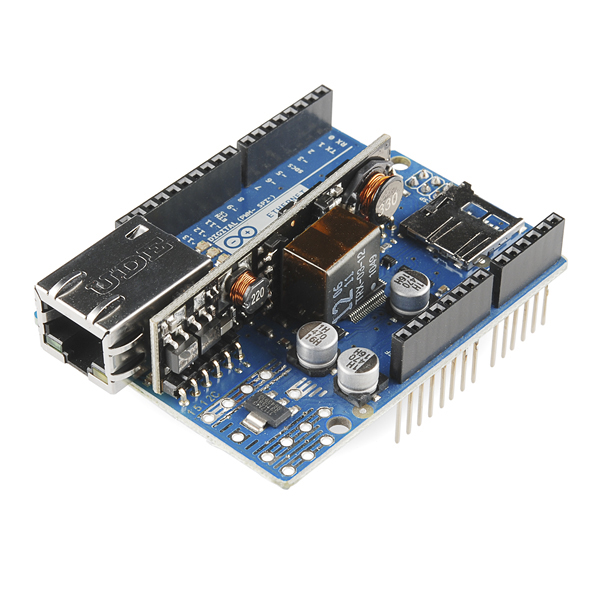
£160 for 10 units, not including the network shield!
Or you could get an Arduino with built-in network and PoE, such as the excellent EtherMega. These are wonderful, but this is even more expensive.
Finally you could get your own chip and include this in a project but it’s still about £6 per unit, see Silvertel Ag9800 themal protected 12vDC module.
Passive PoE – pros and cons
Pros
- Reduced complexity for your project. No inherent need for power negotiation electronics, or step-down converters (unless you want to)
- Far cheaper. PoE passive injectors cost £20 for 8 ports. You supply your own power supply. Of course, no extra electronics at the device end, so it will support most things that come with their own power supply. Your Arduino project may need no special electronics, depending on how you implement it. In my case I added step-down voltage at the other end, read on for more info.
Cons
- Most devices want to run at 9, 12, 15, 18v DC. At these lower voltages, the power loss over cables is significantly higher. This requires thought about two things:
- Electricity bills – are you wasting money?
- Power tolerances – will your device work reliably if running from a slightly lower voltage?
- An extra hub in your comms cabinet = double the number of patch cables = more mess
Which is best?
So which is better for Home Automation? Looking at the Passive PoE cons, I can live with the extra mess, but really how much power is lost over a CAT6 cable?
Joule’s Law
If we can minimise power loss, perhaps we can justify the cheaper option as our cable runs in the home won’t be so long. Let’s take a closer look.
According to Joule’s Law, if we keep the voltage high then DC electrical transmission power line loss will be low. So the first thing we want to do with passive PoE is get the voltage as high as we can (within reason – we are talking low voltage systems here!)
On the other hand, the higher the voltage on your Arduino, the less efficient the conversion down to 5V will be, this is because your Arduino has a linear voltage regulator which is not wonderfully efficient. Also the harder you drive that voltage reg, the hotter it gets. And don’t forget the acceptable voltage input range that your particular Arduino can handle – check the data sheet!
As you can see it’s a trade-off. The best option is to use a non-linear voltage regulator, aka a switch-mode power supply or buck converter. Obviously this is places at the same end of the CAT5/6/7 as your Arduino, so you can benefit from lower power loss over the cable.
Pros of using a separate buck converter to power your arduino over ethernet:
- Doesn’t get as hot = safer for home installations
- Doesn’t waste as much power in the conversion down to 5V. Buck converters are typically 95% efficient. Linear regs’ efficiencies depend on a number of factors such as how hard you drive them, but they are generally 50-70% efficient. (I’ve pulled these numbers from the air!)
- Means you can put a far higher voltage down the line, e.g. some small buck converters can take 30V down to 5V without getting too hot. This in turn means less wasted power because of Joule’s Law.
Cons of using a separate buck converter
- Introduces another component that takes up space on your circuit board or project board
- Can introduce EMI (electric noise) to your circuit, which means you need to be careful about how you design your circuit, and how you lay out your circuit board.
For an excellent introduction to buck converters, check out the videos of Julian Ilett or Afrotechmods on Youtube.
For the sake of answering my own question above, “how much power is lost over a CAT6 cable”, I measured 12V down a 20m cable sinking 400mA at the end of it, and the power had dropped 0.9V. This is fine, but it will vary for cable runs, so let’s run at a higher voltage and not use the Arduino’s in-built linear regulator.
In the end I found this lovely little device on eBay. You can pick them up for £8.30 for 5 = £1.66 each including shipping. Search for “Ultra Mini DC Buck Converter”.
Strangely the auction says “12V to 5V Power Supply 7-22V to 5V”. I think that means you can get them in various flavours outputting anything from 12V to 5V. Lower down on the auction it says “Output Voltage: DC 5V”, so that’s okay. I tested them before I hooked them up and the voltage was a very reliable 5V… although I didn’t test with different current draws, only about 550mA.
Incidentally if anyone with an oscilloscope has used these before, let me know how clean the output is.
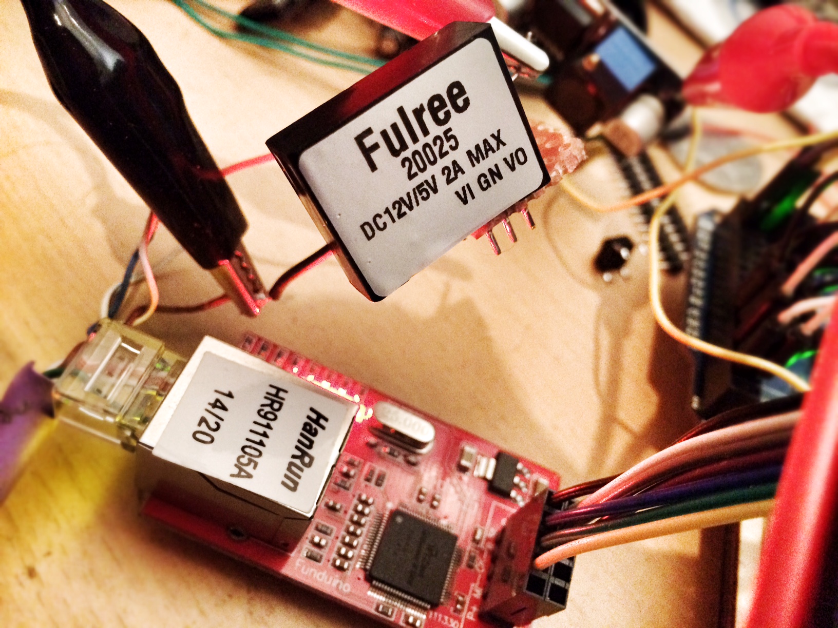
They also come in 1A and 2A flavours, I plumped for the 2A versions of course. I’m sceptical about driving 2A from it and I don’t plan to do that ever!
This “Fulree” branded cheap buck converter seems like the same thing as one you can get from Sparkfun:
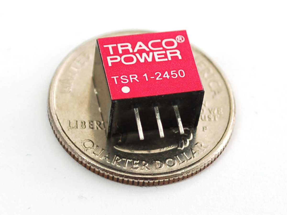
I’ve no doubt the “Traco Power” branded one, also available from Farnell, is superior in quality, shielding, and design. But it’s £5 and I’m a complete cheapskate. (i.e. I’m making 20 of these things and every little saving will reduce my total project cost from thousands to hundreds.)
You could also buy another type of buck converter, even cheaper but not as compact. It exposes the whole circuit on a board of its own and is based on the LM2596 switching regulator. If you do, make sure to watch Julian Ilett’s warning video on not getting a dodgy version:
The other alternative is to include your own buck converter circuit in your project using components from scratch, but there are some design challenges you must be aware of and the components stack up to be more like £3-4 – not worth it. See this beautiful Youtube vid from Afrotechmods for more info.
What cable to use with DIY PoE?
We don’t normally bother about cable gauge when it comes to CAT6, as performance is more about minimising cross talk, shielding, and data transmission speed – not wire thickness. Well, of course the latter does affect the former, but either way for the pursuit of low cost PoE, we must consider this.
Do get good quality CAT5/6/7 cable – preferably CAT6 minimum for PoE. I measured a single strand of my CAT6 cable. The cable measured 0.6mm diameter on my Vernier scale, which is approximately equal to 23AWG. I’m using LSZH (low smoke zero halogen, aka LS0H) infrastructure cable, that is, rigid non-stranded cable that can bend a few times but is not designed for regular movement. Good for home installation if a little rigid. It cost £100 for 305m reel from a local electrical reseller.
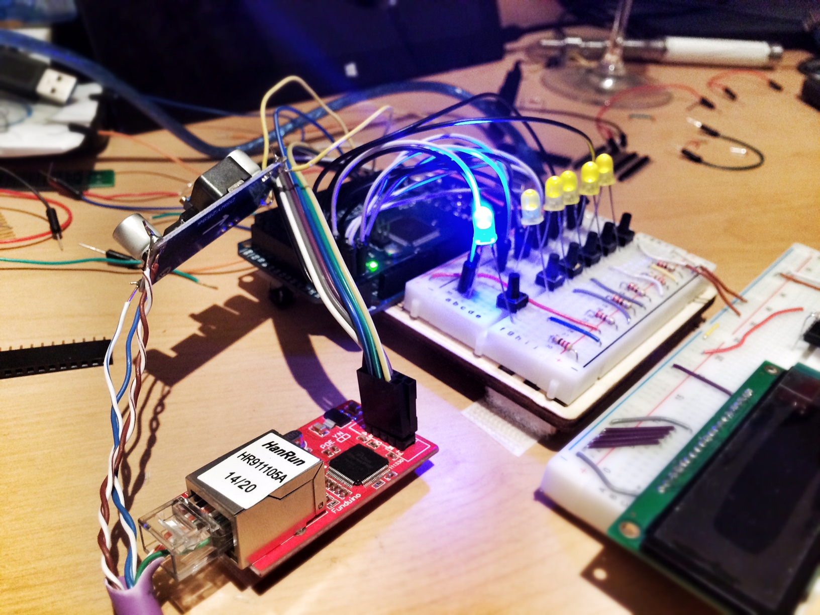
My wall controller project
After a whole load of price checking and electronics research, I decided on this solution for powering my Arduino over ethernet:
- Standard network switch
- Cheap 8 port PoE injector (£20 each)
- Re-use old Dell power supply (free if you have them already)
- 19.5V = perfect for longer runs
- High power (90W or 60W), high quality
- 90W split 8-ways is 11.25W per port
- Almost certainly enough for your project, unless you are powering motors or lights
- P = VI. My project uses max. 450mA at 5V, so that’s 2.25W.
- 2.5W. Don’t forget to do a back-of-fag-packet calculation for power loss and include a lot of headroom. Include line loss, and assume 5-10% loss in the buck converter
- Chop connector off and replace with 2.1mm connector
- CAT6 LSZH
- Fulree buck converter at Arduino end. Connect both browns to GND and both blues to IN (check wiring standards and verify this yourself!)
- Split ethernet cable at Arduino end and use PCB block connectors. I may develop this to route power through the W5100 board in the future, but right now this works for me.
- Connect output of buck converter to Arduino’s 5V connector.
I do have a PoE switch at home, but given the amazing cost benefits of the above option, and the fact it makes a big noise, I’m not going to use it for my project.
Leave a Reply