Here’s a quick hookup guide and sketch to get the ER-OLEDM032-1W display to work with Arduino. We are going to use the u8g library to drive the OLED.
The ER-OLEDM032-1W is a 256×64 graphic OLED module costing $26.56. White on black. I bought mine from eBay although the Chinese brand BuyDisplay.com sells them directly.
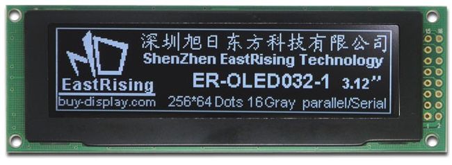
There are two versions of the display, one including the integrated PCB (above) and one without. We want the above one, with integrated PCB. Make sure you purchase the one with the M in the part number.
Here’s a link to the data sheet.
About the part number:
- ER stands for “East Rising” the manufacturer
- OLED stands for OLED: “organic light emitting diode”
- The M stands for “module”. I think. They do two versions, the one with driver board (adapter board) which is this one, and one without the driver board which doesn’t have that M. Confusingly they call the one without a driver board module an OLED module as well. Either I’m wrong or their naming convention is confusing. Or both. Either way you probably want the one with the M, it has an integrated PCB.
- The 032 stands for 3.2 inch, corner to corner
- Not sure what the 1 stands for, they all seem to have it
- The W stands for white, they have other colours (yellow, green blue)
To use the display with u8g library and Arduino you must swap the tiny resistor on the back in position R18 to the position R19. Do this with a steady hand, some really good tweezers and a soldering iron.
ER-OLEDM032-1W Display hookup
swap 0 ohm resistor from R18 to R19 on rear of display
1> gnd
2> 3.3 OR 5 ok
4> level conv – arduino 4 (clock)
5> level conv – arduino 5 (data)
7-13> gnd
14> level conv – arduino 7 (command data select i.e. D/S)
15> reset – this needs to be connected to +5v
16> level conv – arduino 6 (chip select)
For the level converter I used this very cheap module, a clone of something by Adafruit: http://www.ebay.co.uk/itm/Pop-IIC-I2C-Logic-Level-Converter-Bi-Directional-Module-5V-to-3-3V-For-Arduino-/381311755120?hash=item58c7f3a370
And here’s a sketch. I ripped this from a larger sketch I have been working on and haven’t tested it, but it should all be about right.
#include "U8glib.h"

#define oledClock 4 // OLED
#define oledData 5 // OLED
#define chipSelect 6 // OLED
#define commandDataSelect 7 // OLED

U8GLIB_NHD31OLED_2X_GR u8g(oledClock, oledData, chipSelect, commandDataSelect);

void setup()
{
// Setup U8G
if ( u8g.getMode() == U8G_MODE_R3G3B2 ) u8g.setColorIndex(255); // white
else if ( u8g.getMode() == U8G_MODE_GRAY2BIT ) u8g.setColorIndex(3); // max intensity
else if ( u8g.getMode() == U8G_MODE_BW ) u8g.setColorIndex(1); // pixel on
else if ( u8g.getMode() == U8G_MODE_HICOLOR ) u8g.setHiColorByRGB(255,255,255);

....

}

/******************************************/
/* CONTROL DRAWING */
/* --------------- */
/******************************************/
void drawControl(void) {

** insert logic to draw different things here, e.g. as follows **

// Draw current room light level
if (showlightlevel == 1) {
u8g.setFont(u8g_font_6x10);
u8g.drawStr(178, 30, "Currently");
if (lux < 20) {
sprintf (buff, "%i%s", lux, " (dark)");
} else if (lux < 100) {
sprintf (buff, "%i%s", lux, " (med dark)");
} else if (lux < 400) {
sprintf (buff, "%i%s", lux, " (med bright)");
} else if (lux < 10000) {
sprintf (buff, "%i%s", lux, " (bright)");
}
u8g.drawStr(178, 40, buff);
}
}

void loop()
{
u8g.firstPage(); // START U8G
do { // START U8G
drawControl(); // START U8G

** insert the rest of your sketch that does stuff **

} // END U8G
while( u8g.nextPage() ); // END U8G
}
Leave a Reply