I’m going to cover exactly how I flashed my BW-RC1 IR blaster. My reference was this article by Matthew Harrold, which pretty much says the same thing as I’ll write about here, but I’ll try to (a) include some more photos, (b) more specific instructions, (c) cover the process of flashing, and (c) how to actually use it once it’s flashed as it wasn’t immediately obvious to me. In actual fact it is really obvious, but if you’ve never used an IR blaster before then I guess it may help. But thanks to Matthew for blazing the original trail.
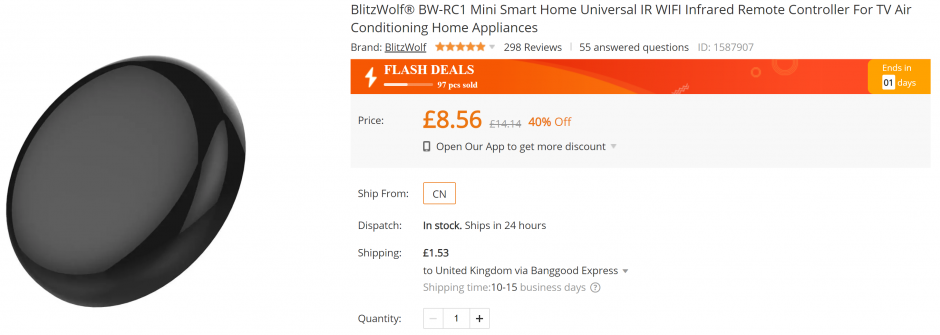
Most people report that this device has new firmware, meaning it can no longer be flashed over the air with Tuya Convert. Hence needing to open the device up.
Let’s jump right in.
What you need
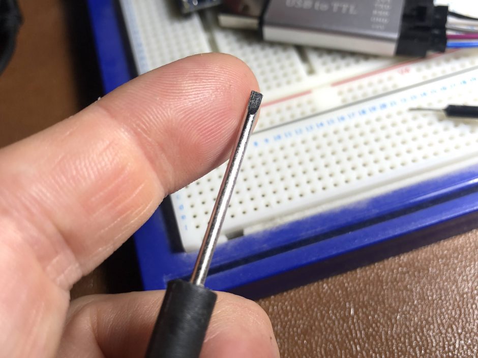
- One tiny flat head screwdriver or similar. This is to slip under the cover to open it up. Head must go to a fine point, hence plastic isn’t so good here, and larger prying tool may not work.
- Another object to shove in to hold it half open while you move your prying screwdriver around. I used a blue plastic prying tool – it snapped but got the job done – you can use any old screwdriver, bigger is fine.
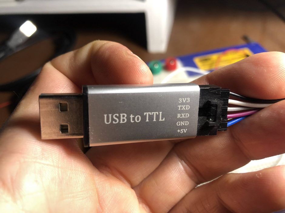
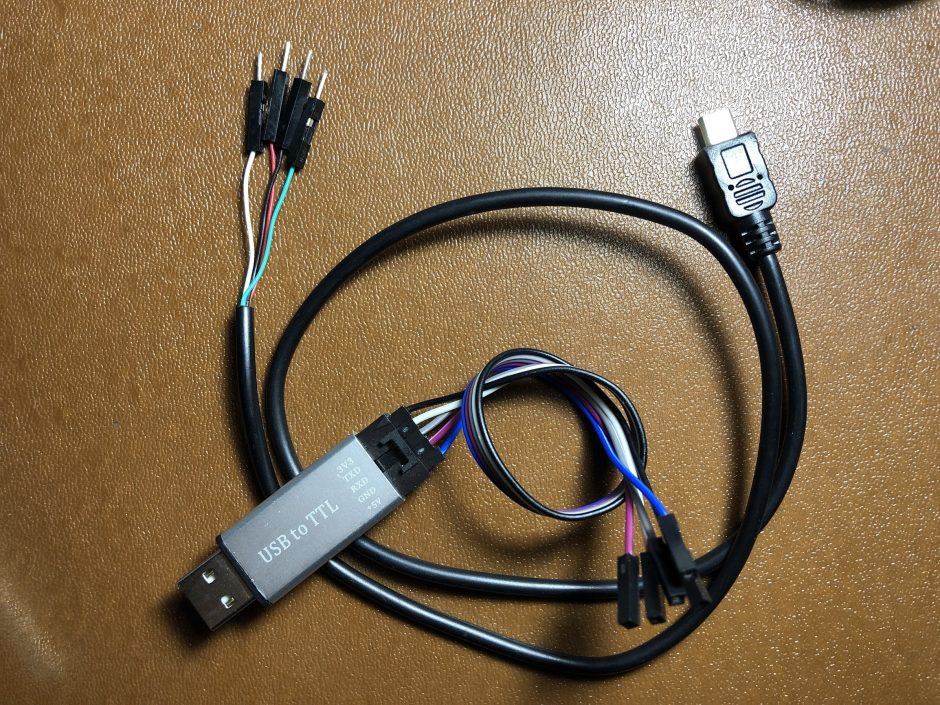
- USB to TTL adapter. AKA a USB UART. Matthew Harrold’s blog says it needs to be 3.3V compatible, technically this is correct however I found my bog standard 5V one worked fine, this was after googling for 5V tolerance on the chip we are flashing. (I didn’t find the answer for the chip inside this thing, the TYWE3S chip. But the similar ESP8266 is known to have 5V tolerant IO pins, not necessarily officially so, but many users report this is fine, so I took the risk and it worked for me in this case. Do this at your own risk of course.)
- A spare USB cable you don’t mind cutting up
- Optionally a breadboard, soldering iron to tin the wires, DuPont crimper, but you could probably improvise if you don’t have these things.
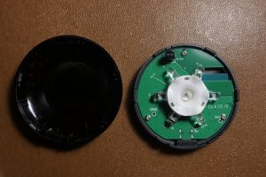
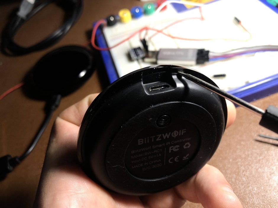
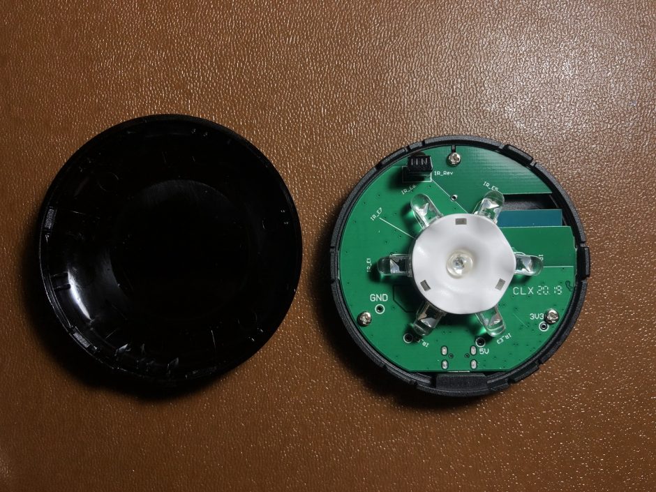
Step 1 – Open it up
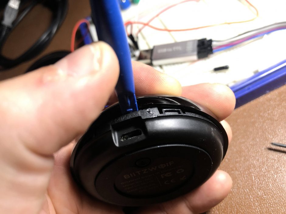
To avoid breaking the tabs, insert a tiny screwdriver just to the right or left of the micro USB:
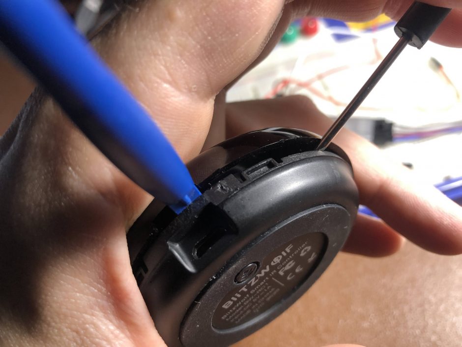
Now you should have missed the tab, so you can hold it open here with something else, then gently pry with your main prying tool to the right of this tab:
Step 2 – connect your USB cable
TL;DR – just connect the UART or USB-TTL adapter up to the micro-USB socket in the Blitzwolf, but swap the data pins around.
Okay so now cannibalise a micro USB cable, I used my lovely new Dupont Crimping Set (highly recommended by the way) so I could keep it for future use.
If you don’t have the means of making up your own Dupont connectors or can’t be bothered, you don’t need to of course. Just improvise. Bear in mind the cores of a USB cable are super thin, so you may find even after tinning with solder that you can’t insert into a breadboard. You could of course use Wago connectors or whatever you like…
Connect the two cables to each other as follows:
Micro USB Red -> TTL adapter +5V
Micro USB Black -> TTL adapter GND
Micro USB Green (Data +) -> TTL adapter RX
Micro USB White (Data -) -> TTL adapter TX
The Blitzwolf needs 5V power through the USB cable, and as mentioned above technically the chip inside which is wired directly to the Data + and Data – of the USB connector needs 3.3V. You could use a level converter for the data pins, or take the risk like I did (I don’t think it’s a big risk!) and connect directly to the TTL adapter plugged in to your computer (5V).
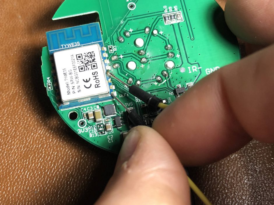
Step 3 – plug it in
Short D0 to GND before plugging in, in order to flash the device. See pic below.
I soldered a wire on, as I don’t have three hands. You may be fine in this area, but it’s biologically unlikely. (Alternatively you may have a friend, that doesn’t apply to me…)
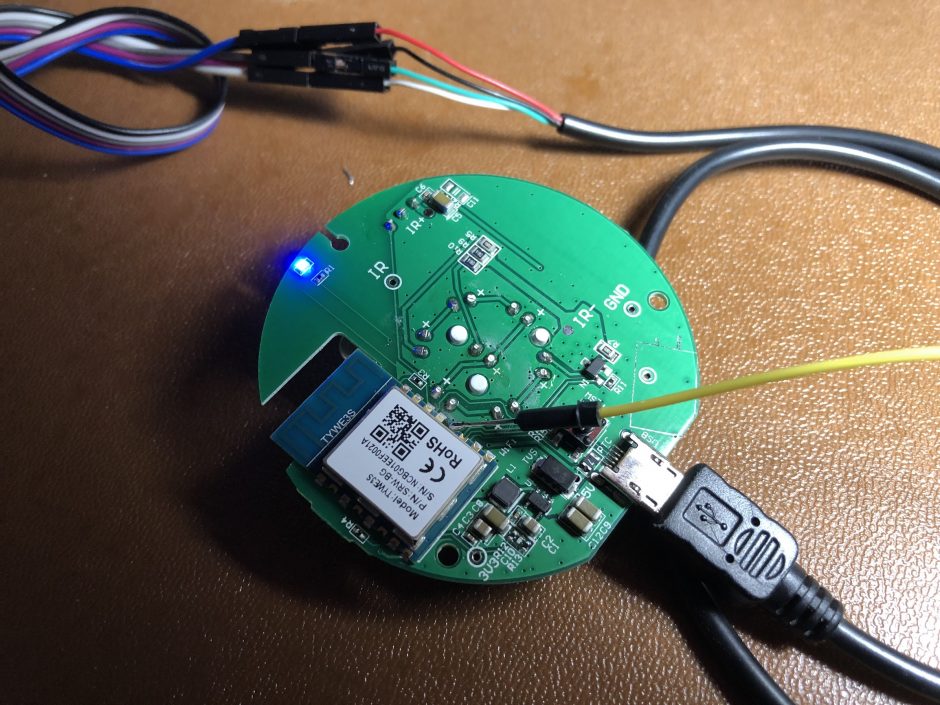
If the little blue light comes on, then it is NOT ready to flash – try again:
Hopefully you are now in flash mode. I don’t think this mode times out after 30s, I was able to flash 4 minutes after powering into flash mode.
Step 4 – Tasmotize!
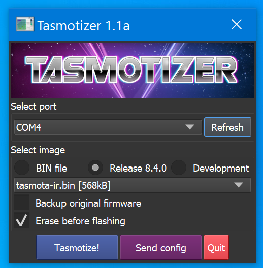
Are you using this Tasmotizer software? You should be! Previously I used various other tools to flash Tasmota, but this works right out of the box.
If your COM port isn’t showing then your USB-TTL adapter isn’t plugged in or you need to reboot Windows because Windows is just like that.
Select the Release image tasmota-ir.bin and hit Tasmotize:
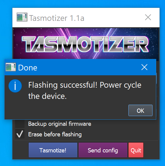
Hopefully you will see this when it’s done:
Step 5 – Configure
TL;DR See below for a cool Backlog command that does all the configuration in one go. I’ll explain it as I go.
- Disconnect then reconnect the device from your computer to power cycle (no need to enter flash mode again by shorting out the pins as before, this may be obvious to you but writing here anyway).
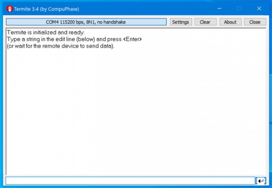
- Downlod Termite, or your favourite terminal program and connect to the COM port at 115200 bps, 8N1, no handshake – same same for pretty much any device you flash with Tasmota.
Here’s the Backlog command I used, I’ll explain in detail below. If you want to just go ahead and fill it in and issue the command in Termite, then you will need to customise it with your network settings and preferences.
Backlog ipaddress1 192.168.1.100*; Topic irblast-001*; DeviceName irblast-001*; FriendlyName1 irblast-001*; SSID1 homewireless*; Password1 blahblahblah*; ipaddress2 192.168.0.1*; ipaddress3 255.255.255.0*; IPAddress4 192.168.0.1*; MqttHost 192.168.0.10*; FullTopic sonoffs/%topic%; TelePeriod 60; Template {"NAME":"BW-RC1","GPIO":[0,0,0,0,56,51,0,0,0,17,8,0,0],"FLAG":0,"BASE":62}; Module 0; SerialLog 0;
*obviously, change these options according to your own needs. I set the device name, friendly name, and topic to be the same, for simplicity.
(The order that my commands are in above may seem illogical, but I do it that way so that I can repeat for multiple devices and only edit the first 4 commands.)
The Backlog command basically allows you to combine multiple commands into a single line, separated by semicolons. Without this, you’d have to wait for reboots between certain commands… so this is quicker and more direct.
- ipaddress1 = IP address of the device you are configuring, i.e. the IR Blaster.
- Topic = MQTT topic. I don’t really like the way Tasmota deals with topics, because this Topic command would imply it’s the whole topic, but actually it’s only a part of the topic. Hence the command “FullTopic” below.
- DeviceName and FriendlyName = I like to set both of these things to match the Topic, for the sake of simplicity
- SSID and Password = your wireless network info, of course
- ipaddress2, 3, and 4 = correspond to your default gateway, subnet mask, and DNS server
- MqttHost = your MQTT server. You do have one, right?
- FullTopic = I have a really nice way of arranging topics, it matches certain other devices like my Shelly devices, as well as my Arduinos. I suggest this format. I’ll explain below how to listen to the device over MQTT and send commands.
- TelePeriod = this is how often the device reports its status to the MQTT server. Default is 300 seconds, but I prefer 60 seconds. You can change this of course.
- Template = this is what tells Tasmota to work with your Blitzwolf infrared blaster. I found this here.
- Module 0 = this actually sets the Tastmota into the template we added above
- SerialLog 0 = turn off serial logging, as recommended by Matthew Harrold on his blog
Of course, if you need other commands e.g. your MQTT server has a username / password, just refer to the Tasmota command reference.
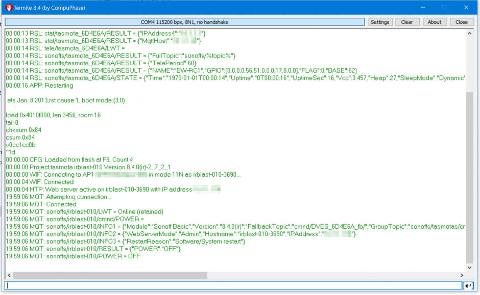
With a bit of luck, you’ll get a response from Termite. If not, you need to power cycle it.
In my case, I power cycled it, and still didn’t work. So I re-flashed, then reconnected in Termite, and it then worked. You should get a response to the above Backlog command:
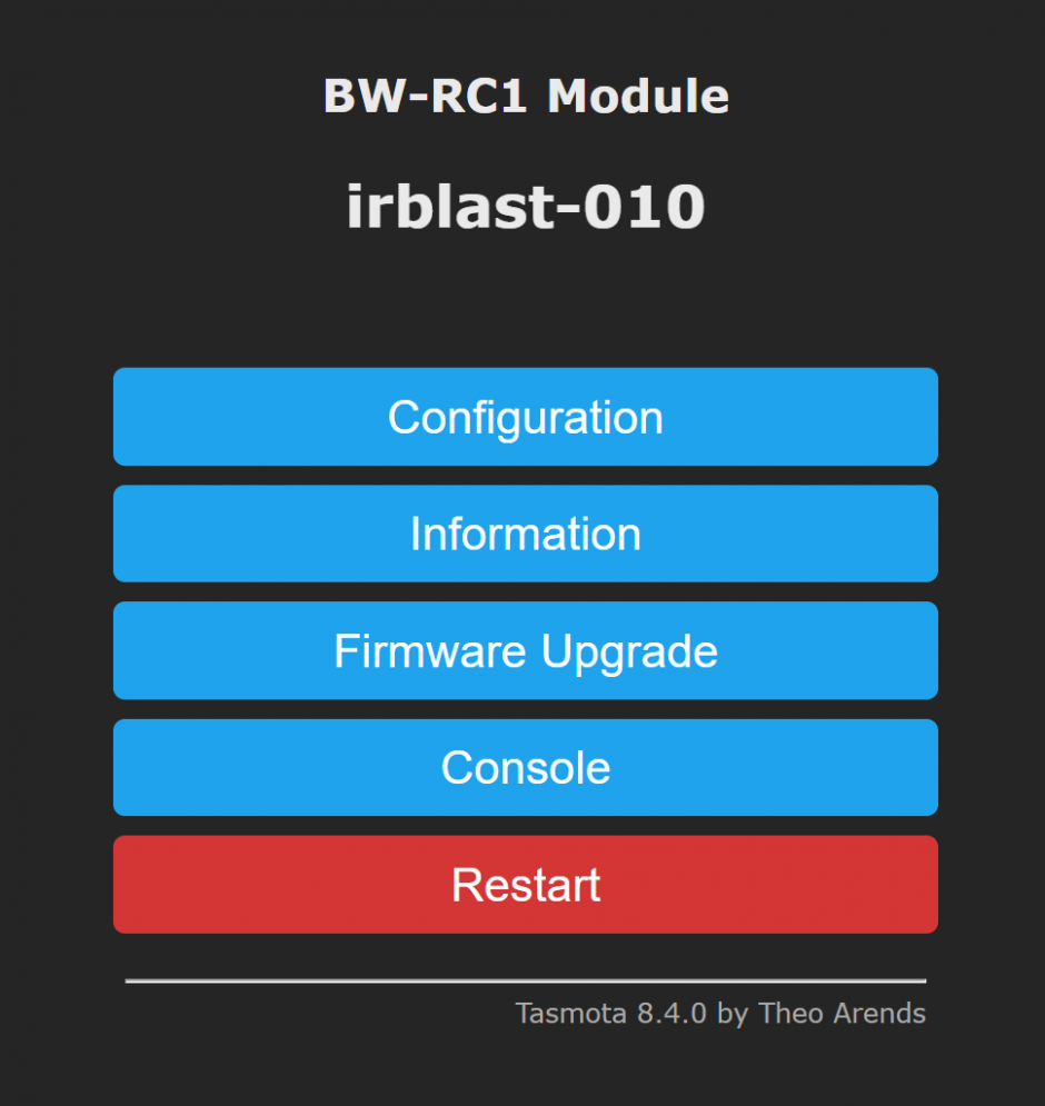
It will reboot itself, now pop the IP address you specified above into a web browser and it should look something like this:
Step 6 – Finishing Up
If you soldered a wire to connect D0 to GND as I did, then de-solder it now. Important: don’t be tempted to just pull that wire off, because the connection was so tiny it will probably come off with a tug. It will pull the pad off the chip.
Pop the three screws back in and clip the front cover back on and you’re good to go! (I forgot the screws in one of mine, makes zero difference as the board is clipped in nicely without them…)
Step 7 – Using the IR Blaster with your automation hub
TL;DR – point your TV remote or whatever signal you want to “learn” at your newly flashed blaster, press a button, and listen to the MQTT topic. You’ll see a code, which you can then use to send back to the command topic. Simple as that!
I used Node-RED as my automation hub, and I make extensive use of MQTT for literally everything in the home. Air con, garden lighting, heated electric blankets – you name it.
As first I thought I’d have to somehow put the IR blaster into “learn” mode then it would store its infrared codes in memory somehow. But that is not how it works. It’s a kind of “dumb” device, you listen to codes in your automation hub, then send out codes from the automation hub. Nothing is stored in the blaster itself.
If you used my MQTT topic convention above, then listen to the following topic:
sonoffs/irblast-010/RESULT
If you changed the Topic / FullTopic in that Backlog command to something else, then change accordingly.
Press a button on your remote pointed at the blaster, and you should see a message coming in to your automation hub e.g.
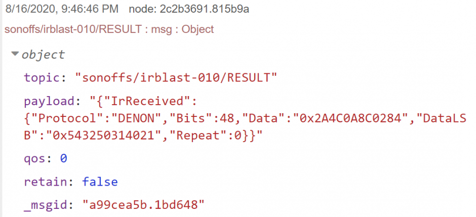
I struggled finding out how to send an IR message, because I wasn’t so familiar with Tasmota commands over MQTT other than on and off. I didn’t realise the command itself (IRsend) needs to be part of the MQTT topic as below. I had thought the command would be send as part of the message. Anyway now I know, and so do you:
Topic = sonoffs/irblast-010/cmnd/IRsend
Message = {"Protocol":"DENON","Bits":48,"Data":"0x2A4C0A8C0284","DataLSB":"0x543250314021","Repeat":0}
Wrapping Up
Hopefully this is all you need to be able to send IR messages from Node-RED. You could even use the device as an IR repeater, by simply setting up a node that listens to incoming messages and relaying them using the respective topic.
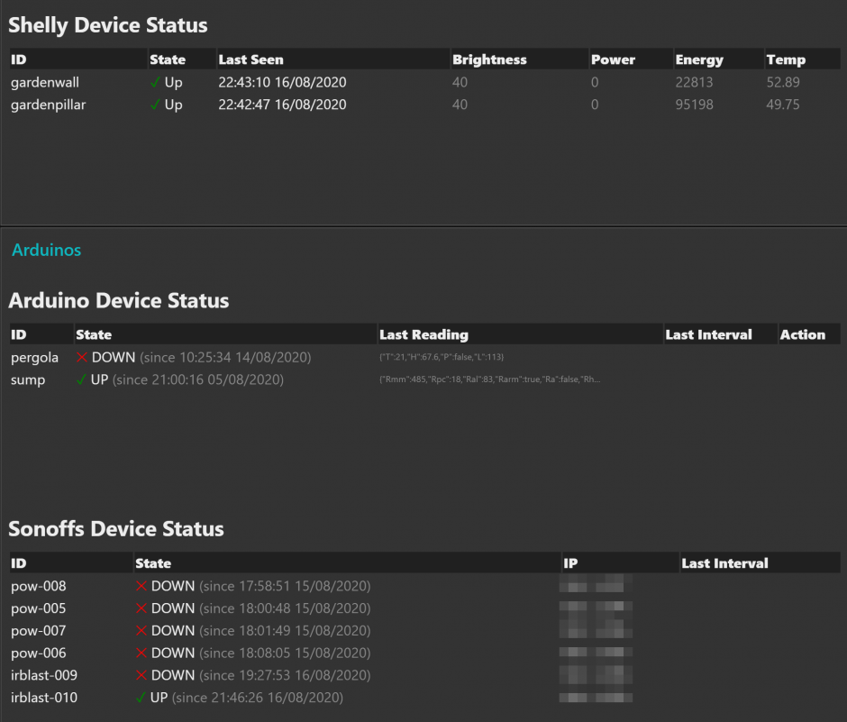
By the way, I’ve written a little Tasmota device register for Node-RED dashboard. It also registers and monitors Shelly devices (which, by the way, was my basis for the MQTT topic convention) and my Arduinos running my own code. Check out the screenshot below, it isn’t fully featured yet but does the basics of monitoring devices. I noticed just now that someone has shared how they dynamically populate the Node-RED dashboard with Tasmota buttons, see here. Haven’t checked that out yet myself, but will give it a try.
If anyone is interested in how I do my monitoring below, then let me know in the comments and I’ll blog about that as well. Cheers!
Leave a Reply