Here’s a new breakout board I have designed and built. If you are interested in any of the following, then read on:
- 8x IO ports via ethernet jacks (6 IO each, plus selectable 5V or 3.3V power)
- Vin up to 24V, with double pole galvanic isolation on the input (to allow e.g. quickly plugging into a laptop without unwiring)
- Wired ethernet for home automation. Sure the ESP32 or ESP8266 are great, but I need to power the device from a central location (yes, this breakout board can use Power over Ethernet) and would rather not have devices that depend on a wireless connection inside my walls.
- a large amount of IO for a low price (48 pins, £5)
- MQTT and cheap sensors
- nice tidy wiring in the home
Vin up to 24V, with double pole isolation on the input so you can plug a laptop in
Suitable for DIY PoE as well!
So I’ve never even used a breakout board before, but I felt compelled to make my own; here’s why.
Basically I wanted a way to get as many IO pins down a good number of CAT5/CAT6 cables as possible, for connecting up many PIRs, temperature sensors, individually addressable LED strips, on-off controls for devices, light sensors, etc., all connected directly to one location e.g. in a wall nearby.
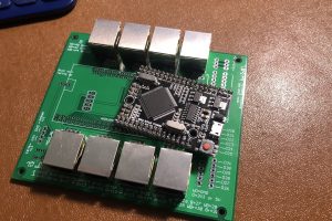
So, the idea. The “Mega 2560 Pro” is a newish board I discovered recently, not an Arduino Mega as such, but a development board based on the same chip, with the same IO (54 pins), and recognised as an Arduino Mega in the Arduino IDE. The key difference is that it’s much smaller (38x55mm) and cheaper (under GBP 5). Of course, with that many pins at that size, it’s not breadboard compatible, hence my breakout board.

I actually discovered this board after buying something that looks quite similar called the Mega 2560 Core. The Mega 2560 Core is great but doesn’t include the CH340 chip, thus needs connecting to your USB via an additional, separate FTDI adapter. Not a major hassle, but this “Mega 2560 Pro” is the same size and includes USB support via a micro USB connector: perfect.
Here’s the spec:
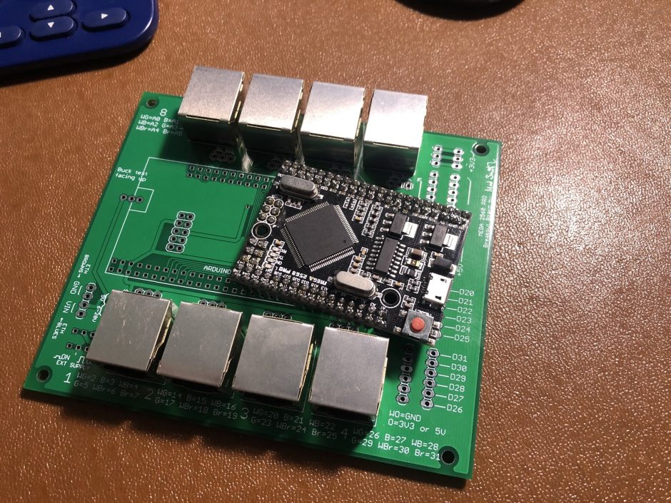
- 48 of the 54 Mega pins broken out into RJ45* sockets for permanent wiring of sensors via CAT6 cable in the home
- Each CAT6 cable also carries power, selectable between 3.3 or 5V (individually selectable for as much flexibility as possible)
- PoE and ethernet connected
- Power via a 5V buck converter, quickly replaceable if it ever dies. (Screwed into a terminal block.) This allows us to use things like old Dell laptop chargers running at 19.5V to power these things from a central location
- Can connect USB whilst it’s powered, as I’ve included a Vin lift button that allows you to isolate the Mega from the input power
- 18 pins are also exposed locally to pin headers AND terminal block connectors for desk tinkering (development) and semi-permanent installs respectively
- Every single CAT cable core is labelled with corresponding Mega pin (e.g. white-green on connector 4 goes to pin 16 or whatever)
(* I think technically if not used for ethernet, RJ45 jacks are called 8P8C connectors.)
It has space for my favourite cheap ethernet board, the Funuino W5100 board (GBP 4 each) and provides a one-stop-shop for prototyping and permanent / semi-permanent installs.
The reason I chose not to break out every single pin is that a) I will always use the ethernet connection, so didn’t bother to break out the pins used by this, and b) I wanted to keep the size down and 8x RJ45 connectors seemed sensible.
For the same reasons, I chose to break out only 18 of the pins locally. After all, if you need to prototype using different / more pins, just use the full size Arduino Mega.
As well as the 18 onboard pins, we also have GND, +5, and +3.3V headers for direct power. Again both by pin header (e.g. for Dupont connectors) and terminal blocks.
RJ45 (8P8C): Each RJ45 takes 6 pins from the Arduino and adds in two pins for power to the remote device(s). The voltage is selectable by jumper: 3.3V or 5V. In reality of course you can’t run 5V over a long cable without introducing too much voltage drop, but this depends on the load and many sensors cope admirably at 5V over 10+ metres: great for ceiling / wall / door / window sensors.
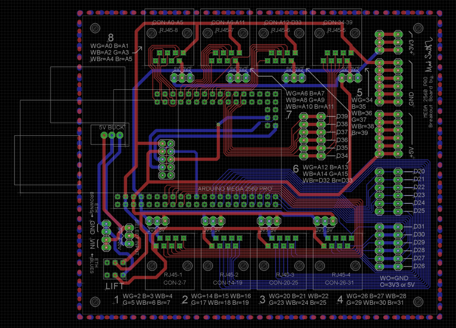
Power: The breakout board provides options for a regulated 5V input OR 6-20V, again by jumper; the latter routing Vin to a little buck converter I seem to have bought lots of called the “Fulree” 5V / 2A switching power supply. It also has a microswitch (double throw latching push button) that allows you to “lift” the Vin to ensure the whole board is disconnected from it, making it easier to plug your USB cable into the Mega without removing the Mega from the breakout board.
Labelling: Finally I wanted the board to be fully labelled, to make it as easy to wire-up as possible. So the DIY PoE terminal blocks are labelled with the words “Blue” and “Brown” to help you remember which is GND and +V, and the pin assignment for each core of the CAT6 cable is labelled according to the colour of the core, assuming you wire your CAT6 to the more common T568B standard: white orange, orange, white green, blue, white blue, green, white brown, brown.
Without further ado, here is the board layout. As mentioned above I don’t have pics of the finished products, as I’m still waiting for them to be shipped from JLCPCB in China, but I’ll update when I do!
Leave a Reply